Internal SPDIF output
Introduction
Joggler uses a IDT STAC9202x5 audio chipset that provides SPDIF output according to datasheet
So, we can easily add a TOSLINK (Optical) socket of Phono socket to take advantage of digital sound :)
Another advantage is that we don't use any USB port to add external sound card with such functionality.
Steps for the TOSLINK socket
Disassembling the Joggler
Check out the following video to disassemble your joggler
Desoldering the jack socket
Desolder the 3.5mm stereo jack socket to make some free space for futur Toslink connector.
Also, don't forget to make the continuities on the PCB to replace the two normaly closed switch of the jack socket.
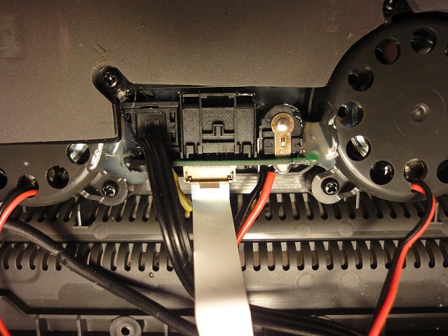
Placing the SPDIF socket
Cut the back plastic cover to fit new SPDIF socket. Solder 3 wires to the socket and then use some glue to fix it on the PCB (or cover)
Soldering wires on motherboard
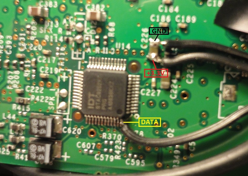
Solder wires from the SPDIF socket to the motherboard.
STAC9202 pinouts :
- pin 7 : GND
- pin 9 : +3.3V
- pin 48 : SPDIF signal
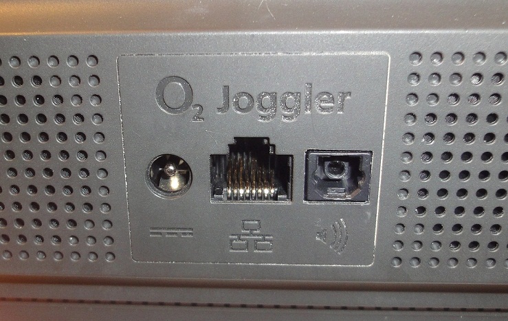
Reassembling the Joggler
You should get something like this on back cover
Steps for the Digital phono socket
Disassembling the Joggler
Check out the following video to disassemble your joggler
Placing the SPDIF socket
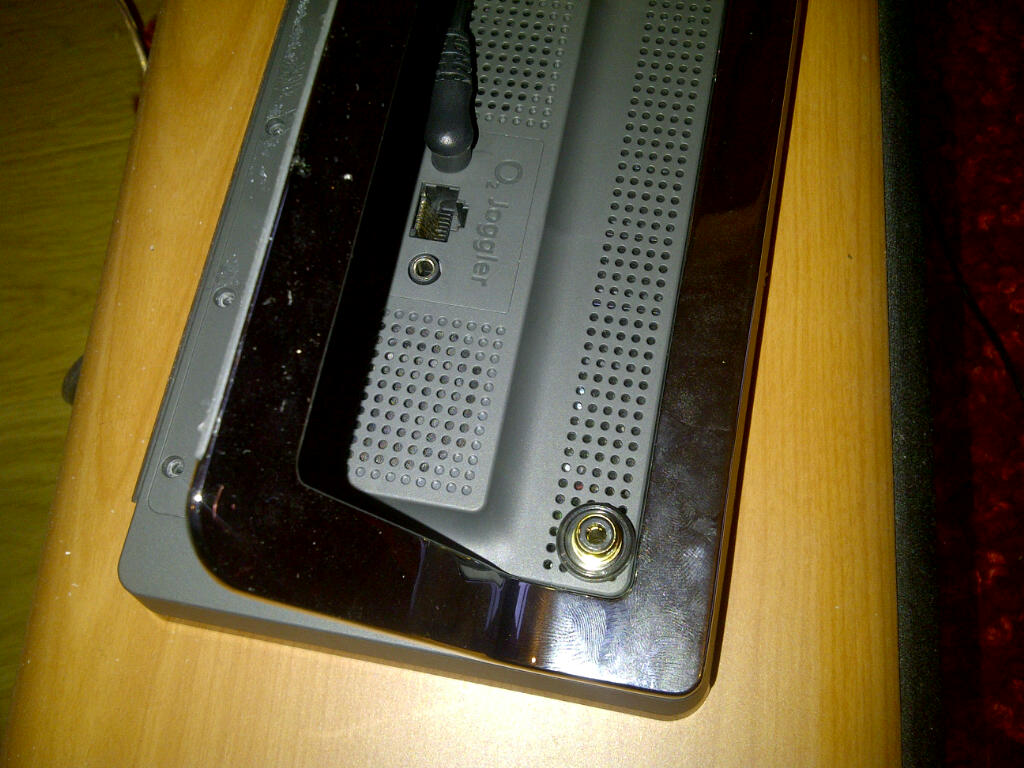
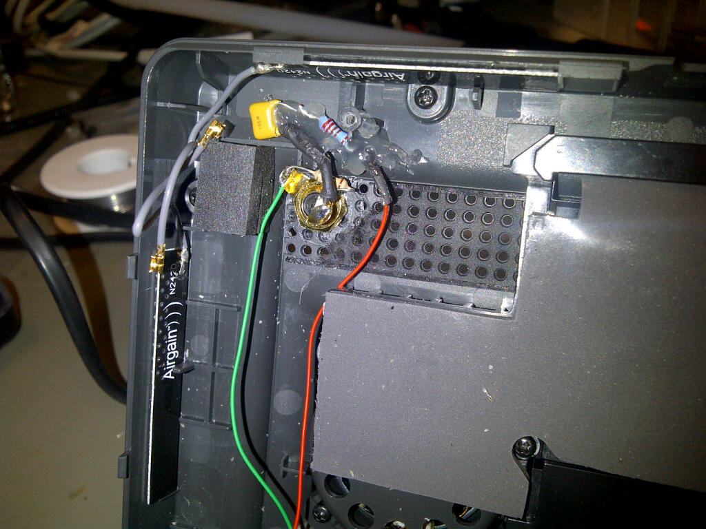
I located the new phono connector in the top left hand side of the rear case. You need to be careful of the placement as it could foul on the wifi card. See the following pictures:
Wiring the Connector
Unlike the TOSLINK Socket a few components are needed between the codec and the connector. These can be built up around the phono socket without much difficulty. The wiring is taken from the codec reference design schematics in this package
The internal photo shows the rough component placement that I used. I placed some insulation tape over everything when I was finished to prevent any shorts:
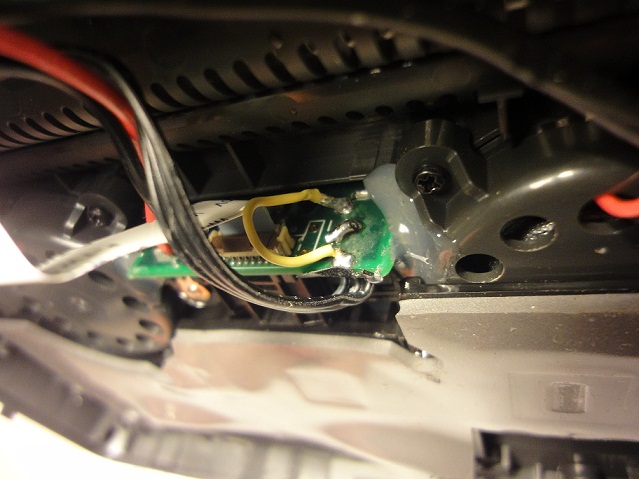
The Signal and ground wires are connected as per this photo (note that the +3.3v wire is not needed for the phono version):
System configuration
These are sound devices available on our Joggler :
 # cat /proc/asound/devices
 2:        : timer
 3: [ 0- 1]: digital audio playback
 4: [ 0- 0]: digital audio playback
 5: [ 0- 0]: digital audio capture
 6: [ 0- 0]: hardware dependent
 7: [ 0]   : control
Card0 / Device1 is spdif digital output. To use SPDIF instead of internal speaker, edit /etc/asound.conf like this :
 pcm.!default {
   type hw
   card 0
   device 1
 }
If you are running with the Roobarb Squeezeplay app on the standard firmware then you may need to change the following line in asound.conf:
slave.pcm "hw:0,0";
To:
slave.pcm "hw:0,1";
Note 1 : If you are using SqueezePlay OS, you just need to ssh to the Joggler, execute alsamixer and unmute SPDIF output (select it and just press 'M' to unmute)
Note 2 : If you are using O2 stock firmware, you have to edit one more file to unmute digital output at startup.
Edit check_snd() function in /etc/init.d/boot.d/S07boot.loadmodules :
 check_snd()
 {
   local LOG="/openpeak/tango/amixer.out"
   echo $* > ${LOG}
   (amixer -c 0 sget 'IEC958',0 | tail -2) >> ${LOG} 2>&1
   local IS_MUTED=`grep "off" ${LOG} | wc -l`
   if [ ${IS_MUTED} -gt 0 ]; then
     echo "Error: Muted Audio!" >> ${LOG}
     amixer -q -c 0 sset 'IEC958',0 unmute
     if [ $? -ne 0 ]; then
       echo "-- Failed to recover --" >> ${LOG}
     else
       echo "++ Recovered ++" >> ${LOG}
     fi
   fi
 }
Reboot the Joggler and enjoy digital sound ;)
PS : Apologies for bad pictures quality
