Additional USB Ports
Why bother?
If you want to plug more devices into the Joggler, the obvious choice is a hub on the external port. This can also provide as much power (from the hub's external power supply) as is necessary.
But you might want to add some internal peripherals, like a Bluetooth interface or a GPS receiver. Or you might want something permanently attached (such as a memory stick to boot an alternate operating system) and not want that sticking out of the side all the time. One very useful addition would be a memory card adapter (e.g. SD card) wired to an internal port but fitted to the back so that a large memory card can easily be connected. Note that this may need changes to the stock application as that only attempts to mount /dev/sda1 - if /dev/sda1 is already there as an internally-wired memory card the applications will ignore further cards fitted to the slot on the side (though they're seen by the operating system as /dev/sdb etc.).
USB Controllers
The SCH US15W device has 4 USB controllers (3 x USB1.1, 1 x USB2.0) and 8 ports. The ports can be assigned to the controllers in various ways, but only 3 are connected to the joggler hardware : one for the external port (bus 1, port 3 for USB2, bus 3 port 1 for USB1.1), one for the internal wifi dongle (bus 1 port 4) and one for the touchscreen (bus 4, port 1).
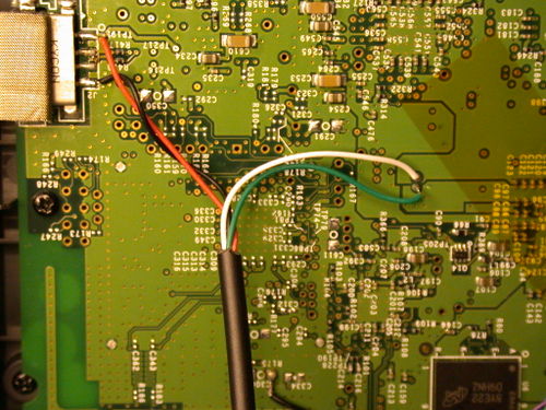
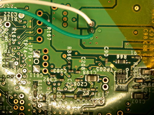
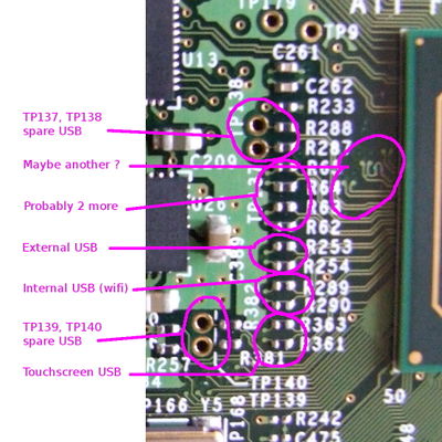
However, examining the PCB near the USB pins appears to show that more are actually pinned out. In particular, TP139 and TP140 provide access to the pins of unused ports and are plated-through holes that are easily connected to wires.
This comes up as bus 1 port 6, USB 2.0 only - a USB 1.1 device isn't visible.
Connecting a memory stick seems to be handled like the other usb connectors - the stock firmware automounted the SD card as /dev/sda1 and another device plugged into the external socket was then manually mounted as /dev/sdb1.
Modifications
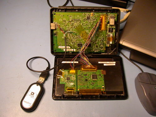
The following pictures show a USB device connected to these pins. I've taken power from the external socket. This is handy but probably not the best place as both devices will be using the same internal fuse. A better method for an external socket would be to tap 5v power from the main incoming power socket and add an autoresetting fuse in-line. Internal devices can probably be trusted without a fuse. Note that you can't just add 500mA USB loads on as many connectors as you want - the power's got to come from somewhere!
Pictures from the back of the PCB (visible with the case open, PCB still in place)
The wire colours used here follow the usual convention :
pin 1, red,   +5V
pin 2, white, D-
pin 3, green, D+
pin 4, black, Gnd
TP137 and TP138 are similar, connected to bus 1 port 0 for USB 2 but will also work with USB 1.1 as bus 2 port 0.
Even more ports
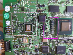
Picture of the component side (remove the PCB to see this). The layout of the tracks gives a clue as to the USB port wiring and checking some of these through to known ports with an ohmeter reveals which ones are used. The remainder are probably free and some are particularly easy to connect as shown above.
The touchscreen uses the blue and green wires for USB - pin 4 and 5 on the original screen connector.
Reported Issues
Display Corruption
"I first wired both of the easy pads as shown in the pictures. I found that during boot while the Linux text scrolled up the screen the screen was unstable with random scan lines - but the Ubuntu screens were OK."
"So I used screened leads with their screens earthed at a square pad near the USB vias - near the 79 of TP79. The noise went away and I could use either of the new USB ports for my external hard disk to boot (Ubuntu from dysentry). But my Logitech optical mouse only ran on one of the new ports."
This will be because that port supports USB 2.0 only - not 1.1, and the mouse will be 1.1. It seems that backward compatibility to support USB 1.1 on USB 2.0 ports actually uses an alternate controller, at least on this hardware - artag
"(I found some a very thin screened wire that was used in a hands-free mobile phone earpiece and microphone that I had no need for - you get a new one every time you upgrade your phone.) My Joggler pages are here http://www.sunspot.co.uk/Projects/Joggler/joggler_top_page.html"
Unstable Ports
This is from a limited sample of four Jogglers, all AO2JOGON models displaying the O2 logo at boot. On two of the Jogglers, MicroSD card readers were soldered to the pins near the C197 label, taking power from the external port as shown above. They work perfectly and reliably, with both systems having long uptimes (weeks). The other two Jogglers, with same model readers bought at the same time, which work perfectly on the first two Jogglers, are unstable on both this connection and the more easily accessible USB2.0-only bus.
The effects manifest as unreliable booting or frequent crashes due to a disconnection of the filesystem. When using devices with LED indicators, the LED can be seen to drop out for a fraction of a second, at which point the filesystem unmounts and the system dies. Measuring the voltage during these dropouts did not show a loss of power (stable around 5.1V).
The problem is easily demonstrated using the external USB port to boot the same MicroSD card reader. In the external port the reader functions perfectly once again. While running Ubuntu from the external port, connecting a USB device to the internal port (using a USB socket lead as shown in the pictures) will usually result in a mounted filesystem, but then over the course of the next few minutes this will repeatedly disconnect and re-mount.
The internal work to these two Jogglers was undertaken using full anti-static prevention measures using a soldering station designed for dissipating electrostatic charges.
Workaround
The only successful method found to fit internal USB devices on these Jogglers has been to install an internal USB hub. Connections to either the external port or the internal port which connects the wireless card have proved to be completely stable on both of these 'problem Jogglers'.
Using the USB hub mentioned in this thread, it needs to be stripped down to its single internal board and new wires taken from the wireless card's USB socket to connect it to the logic board. A good position for the hub is in the upper-right corner of the logic board. If your USB hub board contains a crystal (silver component with rounded corners) it may be necessary to remove this and reattach it on short wires to have sufficient clearance to refit the display.
You will then need to remove the USB plug from the internal wireless card and solder new leads to connect it to the USB hub. You cannot simply reconnect it, as the data lines are in use by the hub. For this reason the external port cannot be used, as this would render it useless for additional devices.
