
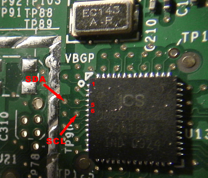
IE: Pin 5 is SDA (data) and pin 6 is SCL (clock)
If the hardware works well together, it will still be necessary to read the time from the RTC module at boot time and at specific intervals to update and keep the Joggler's infamously drifting clock, more or less accurate.Drive an external PIC16F877A using just i2cset and i2cdetect on the Joggler - a test example
The PIC has an array buffer[0x10] and i2cset can load values into it by sending the array element number followed by the value
The circuit is like the left hand circuit at the bottom of this page
e.g. i2cset -y 0 80 0 2 b sends to i2c bus 0 at address decimal 80 and places a value 2 in the array element buffer[0]
In this test pin DO is wired to an LED (then to resistor to ground - so LED on = high )
buffer[0] . . . Set the mode of action. If it is 1 then the LED flashes and if it is 0 the LED is on or off
buffer[1] . . . For the flashing mode 200 means set pin D0 high for 200 milliseconds
buffer[2] . . . For the flashing mode 200 means set pin D0 low for 200 milliseconds
buffer[3] . . . For the on or off mode, 1 means ON, 0 means OFF
Code: Select all
     0  1  2  3  4  5  6  7  8  9  a  b  c  d  e  f
00:          -- -- -- -- -- -- -- -- -- -- -- -- --
10: -- -- -- -- -- -- -- -- UU -- -- -- -- -- -- --
20: -- -- -- -- -- -- -- -- -- -- -- -- -- -- -- --
30: -- -- -- -- 34 -- -- -- -- -- -- -- -- -- -- --
40: -- -- -- -- -- -- -- -- -- -- -- -- UU -- -- --
50: -- -- -- -- -- -- -- -- -- -- -- -- -- -- -- --
60: -- -- -- -- -- -- -- -- -- 69 -- -- -- -- -- --
70: -- -- -- -- -- -- -- --Code: Select all
     0  1  2  3  4  5  6  7  8  9  a  b  c  d  e  f
00:          -- -- -- -- -- -- -- -- -- -- -- -- --
10: -- -- -- -- -- -- -- -- -- -- -- -- -- -- -- --
20: -- -- -- -- -- -- -- -- -- -- -- -- -- -- -- --
30: -- -- -- -- -- -- -- -- -- -- -- -- -- -- -- --
40: -- -- -- -- -- -- -- -- -- -- -- -- -- -- -- --
50: 50 -- -- -- -- -- -- -- -- -- -- -- -- -- -- --
60: -- -- -- -- -- -- -- -- UU -- -- -- -- -- -- --
70: -- -- -- -- -- -- -- --